
Licensed Florida Contractor
FL License #EC13016138 identifies the contracting license presented by Data Pro Communications.
CAMERA INSTALLATION WORKFLOW
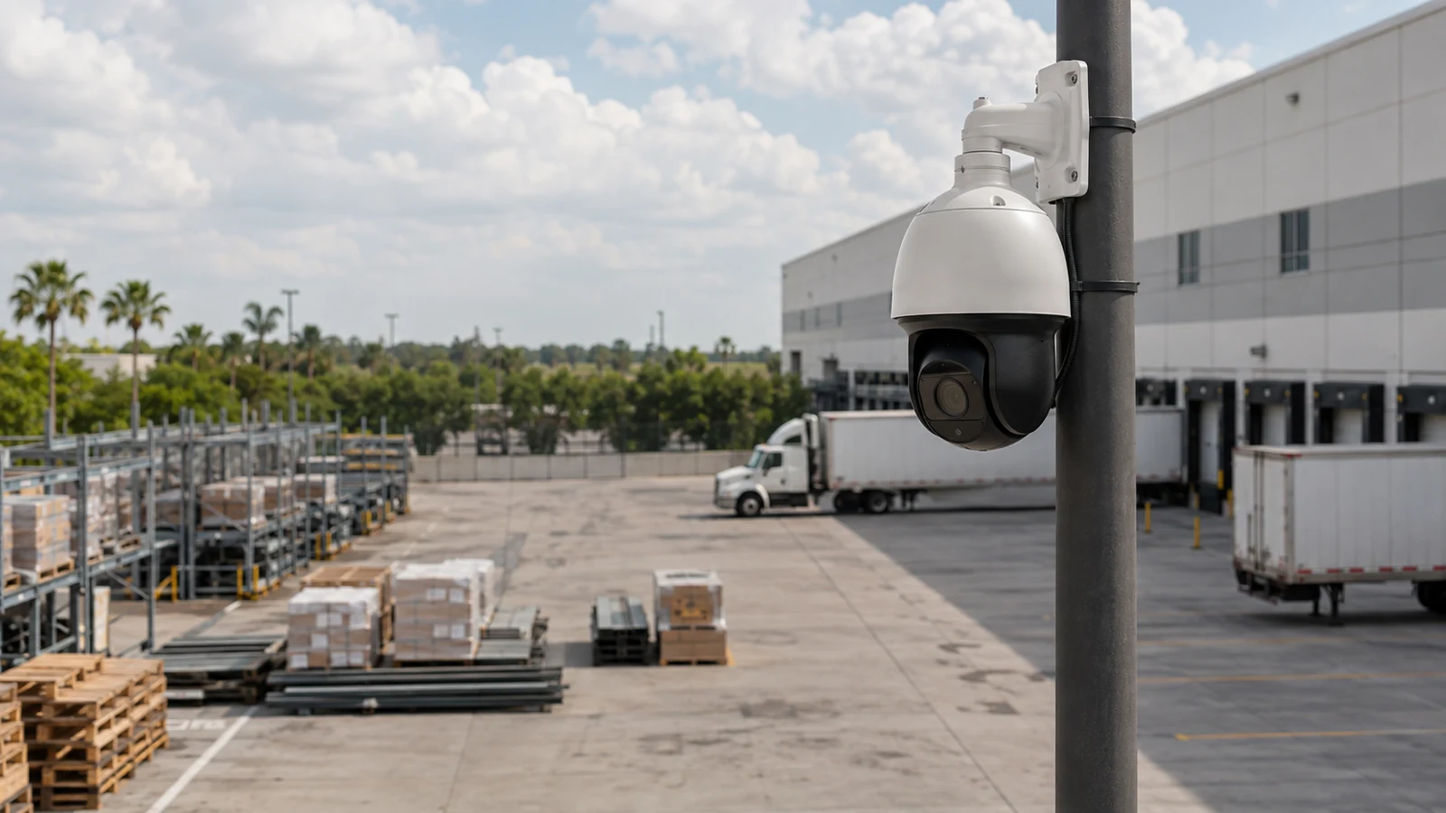
A dependable CCTV installation begins with the event the camera must show, not with a box of devices. The useful sequence is to define each required view, survey mounting and pathway conditions, confirm power and recording capacity, install in a controlled order, and prove that operators can retrieve the evidence they need.
FL License #EC13016138 identifies the contracting license presented by Data Pro Communications.
State whether each view must observe activity, recognize a person, identify a face, verify a transaction, or capture a vehicle detail. The objective determines scene width and mounting position.
Obstructions, backlight and excessive scene width require design changes, not more commissioning.
Named administrators, training audience and service records.
PROJECT GUIDANCE
Treat installation as a chain of dependencies. Mounting height affects scene detail; pathway choice affects serviceability; PoE budget affects stability; recorder settings affect retention; and account handoff determines whether authorized staff can use the finished system. Skipping one link can leave apparently working cameras that fail during playback or maintenance.
CAPABILITIES
State whether each view must observe activity, recognize a person, identify a face, verify a transaction, or capture a vehicle detail. The objective determines scene width and mounting position.
Trace accessible pathways, fire-rated boundaries, exterior transitions, telecom-room capacity and lift access. A route that exists on a floor plan may be blocked or unsuitable in the field.
Calculate PoE demand, switch uplink capacity, addressing, VLAN requirements and surge exposure. Wireless backhaul still needs dependable local power and a supported radio path.
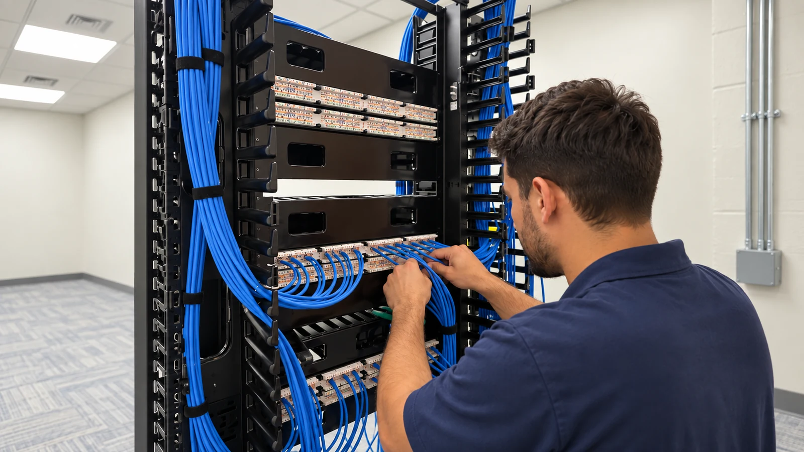
Complete and test cabling before final camera aiming. This separates pathway faults from camera configuration problems and reduces repeated work at height.
Aim and focus under representative lighting, verify timestamps, motion behavior, recording schedules and user permissions, then test playback from the viewing stations staff will use.
Provide camera names, locations, network details, retention assumptions, administrator ownership, export instructions and any unresolved limitations at handoff.
EAST ORLANDO CONTEXT
Occupied East Orlando offices and retail properties often require camera work to be divided around tenant access and active network hours. In Goldenrod facilities with mixed pathway history, cable routes and telecom-room capacity should be verified before mounting dates are committed.
PROJECT GUIDANCE
State whether each view must observe activity, recognize a person, identify a face, verify a transaction, or capture a vehicle detail. The objective determines scene width and mounting position.
Trace accessible pathways, fire-rated boundaries, exterior transitions, telecom-room capacity and lift access. A route that exists on a floor plan may be blocked or unsuitable in the field.
Calculate PoE demand, switch uplink capacity, addressing, VLAN requirements and surge exposure. Wireless backhaul still needs dependable local power and a supported radio path.
Complete and test cabling before final camera aiming. This separates pathway faults from camera configuration problems and reduces repeated work at height.
Aim and focus under representative lighting, verify timestamps, motion behavior, recording schedules and user permissions, then test playback from the viewing stations staff will use.
Provide camera names, locations, network details, retention assumptions, administrator ownership, export instructions and any unresolved limitations at handoff.
PROPERTY APPLICATIONS
Work can be divided by corridor and scheduled around tenant access so ceiling pathways are closed before cameras are aimed.
Cable testing precedes camera mounting; daylight and after-dark views are then reviewed for doors, trailers and approach lanes.
Existing cameras are inventoried first so compatible channels, storage demand and cutover order are known before the old recorder is removed.
PROJECT PROCESS
Give every camera a name, purpose, target area and acceptance condition.
A clear installer laptop view is not enough; confirm search and export on the customer workflow.
Keep junctions, labels and cable routes reachable without dismantling finished work.
PLANNING RISKS
Obstructions, backlight and excessive scene width require design changes, not more commissioning.
Continuity alone does not prove bandwidth, pinout, distance or environmental suitability.
Firewall policy, internet service, accounts and secure authentication must be coordinated with the customer.
PLANNING RISKS
The selected quantity may exceed switch, route or recorder capacity.
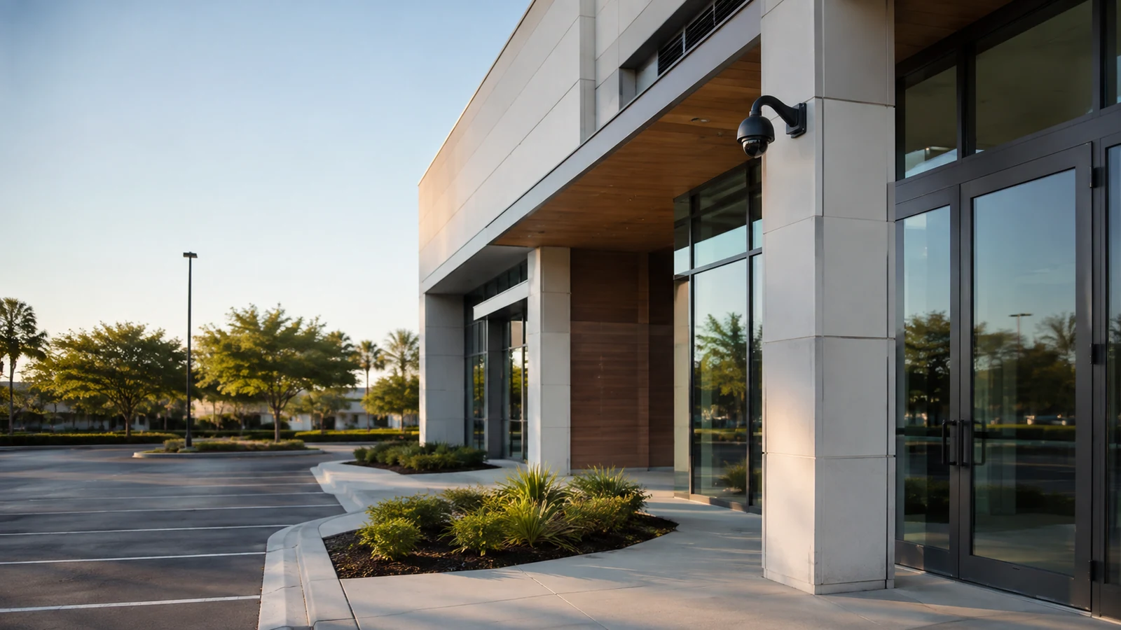
Entrances and exterior scenes can change materially after sunset.
Unclear device identity and unmanaged credentials make support harder and weaken access control.
TECHNICAL PLANNING
Approved route, cable support, penetrations and weather transitions.
Per-port power, total budget, uplinks and network ownership.
Channel licenses, storage, retention and export format.
Named administrators, training audience and service records.
PROJECT GUIDANCE
RELATED PATHS

PROJECT PROCESS
State whether each view must observe activity, recognize a person, identify a face, verify a transaction, or capture a vehicle detail. The objective determines scene width and mounting position.
Trace accessible pathways, fire-rated boundaries, exterior transitions, telecom-room capacity and lift access. A route that exists on a floor plan may be blocked or unsuitable in the field.
Approved route, cable support, penetrations and weather transitions.
Keep junctions, labels and cable routes reachable without dismantling finished work.
FAQ
Define the event, subject and level of detail each view must provide. Those requirements guide scene width, lens choice, distance and mounting position.
The survey exposes route access, obstructions, lighting, power, network and work-zone conditions that cannot be resolved from a camera count alone.
Yes. Testing pathways first helps isolate cable faults and confirms that links can support the planned devices before final aiming work begins.
Review each camera load, the switch per-port limits, the total PoE budget, cable distance and any added devices such as heaters or illuminators.
Verify focus, night behavior, timestamps, recording schedules, retention assumptions, user permissions, playback, search and export.
Often it can, when access windows, ceiling work, lifts, noisy tasks and network cutovers are divided into approved work zones.
Reuse is reasonable only after the cable type, termination, condition, route, distance and required performance are verified.
The customer should identify authorized account owners and define how credentials, recovery methods and service access will be controlled.
Useful records include camera names and locations, cable labels, network assignments, recorder details, retention settings, account ownership and export instructions.
No. Results depend on scene geometry, lighting, equipment capability and approved design choices. Limitations should be identified and tested against stated objectives.
A CCTV installation is complete when required scenes can be found, reviewed and exported by authorized users, and when the pathway and account records make future service practical. Device mounting is only the visible middle of that sequence.