
Florida Licensed
FL License #EC13016138 for low-voltage systems work.
LONG-DISTANCE AND BUILDING-TO-BUILDING INFRASTRUCTURE
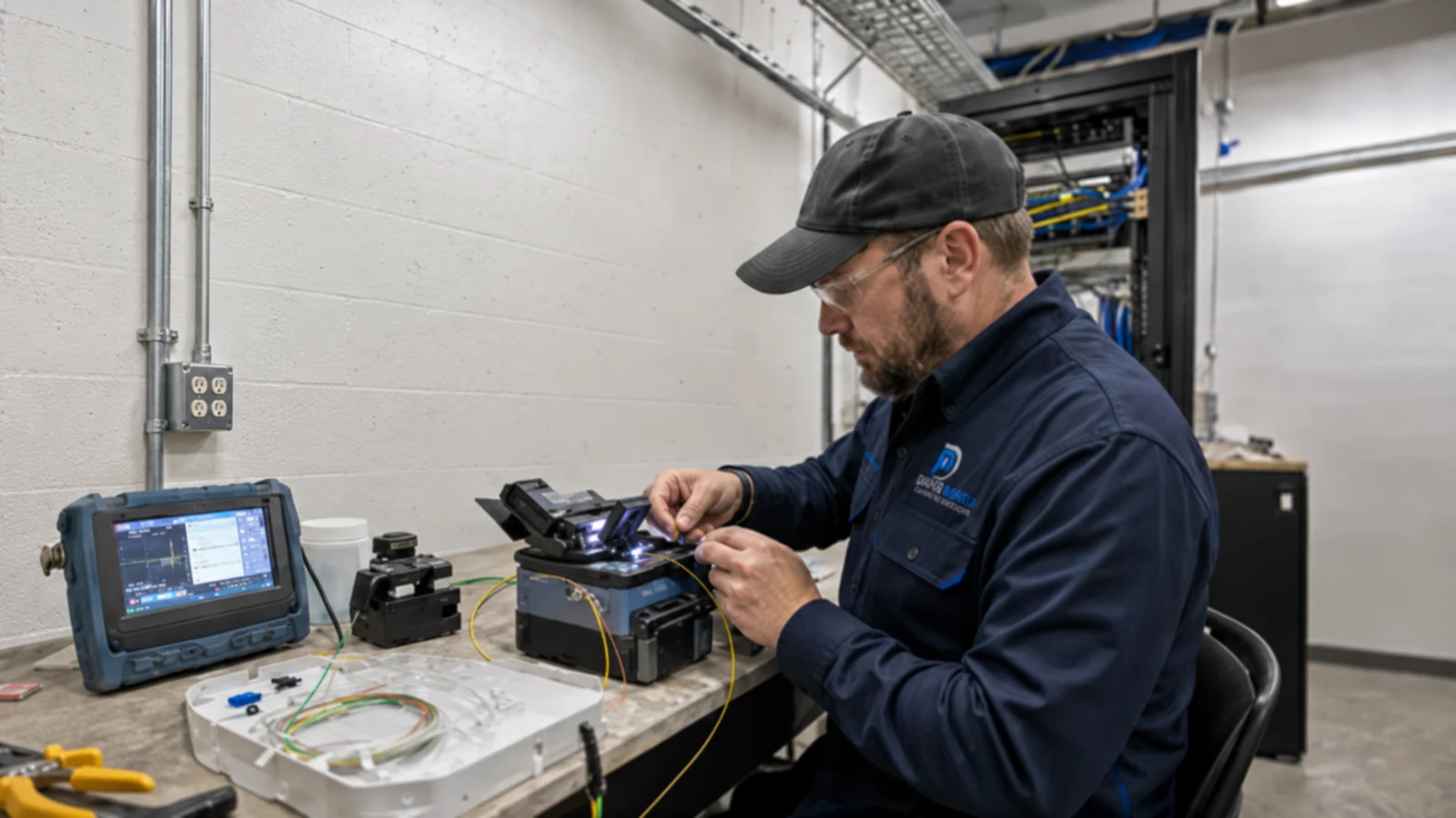
Fiber carries high-capacity links across distances and environments where a copper channel may not fit. The design must connect route, fiber type, strand count, enclosure, splice or termination method, optics and loss expectations as one optical path.
Data Pro Communications installs and documents supported commercial fiber backbones for building links, telecom-room uplinks and low-voltage system transport without reducing the scope to ordinary horizontal cabling.
FL License #EC13016138 for low-voltage systems work.
Used, spare and reserved fibers are labeled by endpoint and service.
Connector inspection and cleaning are part of reliable termination and testing practice.
The agreed end-to-end measurement is recorded against the installed optical path.
Enclosures, slack, patching and interface boundaries remain understandable for future restoration or expansion.
PROJECT GUIDANCE
Fiber planning begins at the two equipment interfaces and works through distance, pathway, environment, strand capacity and serviceability. Single-mode or multimode selection, connector and splice strategy, enclosures, patching, optics boundaries and loss testing should be recorded for the complete link.
PLANNING RISKS
Contamination and scratched end faces can introduce significant loss even when the cable itself is intact.
Single-mode, multimode, wavelength, connector and transceiver capability must match across the link.
Splices, connectors, bends, distance and damaged cable can consume the available power budget.
A backbone with no spare capacity can force another cable installation for a small future expansion.
Crowded or inaccessible splice trays and patch fields increase restoration time and bend risk.
Sharp bends, pull tension, water, construction activity or inappropriate pathway can damage the backbone.
CAPABILITIES
Plan endpoints, pathway, distance, fiber type, strand count, spares and restoration access.
Install approved indoor, outdoor or building-link cable in suitable pathways with pull and bend control.
Prepare supported fusion splices, connectors or pigtails and organize them in serviceable enclosures.
Label trays, adapter panels, cassettes and patch cords by strand and destination.
Measure the agreed end-to-end loss and compare results with the documented path and acceptance basis.
Locate and repair supported faults where route access, spare length, fiber condition and service requirements permit.
PROPERTY APPLICATIONS
Link two commercial buildings where copper distance or exposure is unsuitable.
Explore Detached building connectionCarry aggregated traffic between a distribution floor and administrative network room.
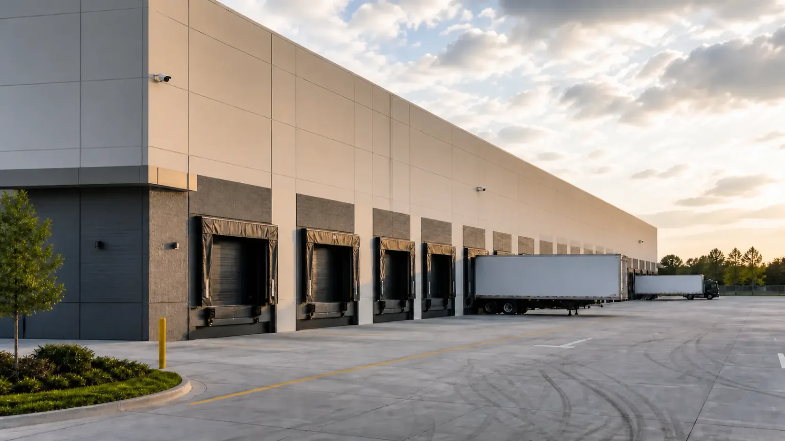
Explore Warehouse-to-office uplinkConnect remote camera or access-control network segments over an optical path without making fiber the camera service itself.
Explore Campus security backboneAdd strands or capacity between telecom rooms when copper uplinks are limiting.
Explore IDF backbone expansionUse suitable fiber and pathway for long runs or electrically challenging environments.
Explore Industrial or service yardRepair a damaged strand or enclosure and retest the affected optical path before returning it to service.
Explore Backbone restorationTECHNICAL PLANNING
Match distance, installed plant, optics, wavelength and lifecycle rather than mixing media by convenience.
Document used, spare and reserved strands by pair, destination and service.
Account for fiber length, splices, connectors and design margin against the selected optical interfaces.
Select cable construction and protection for indoor, outdoor, aerial, underground or shared-route conditions as applicable.
Reserve tray, cassette, adapter and bend-management space for current and future work.
Identify which network switches, media converters or transceivers terminate the optical link and who owns their configuration.
PROJECT GUIDANCE
Fiber provides the optical path between switches, media interfaces or other supported endpoints. Network Solutions owns VLANs, uplinks and active configuration; camera, access or intercom pages own the application traffic. Fiber handoff should document the strands, patching, loss and interface boundary that those systems rely on.
EAST ORLANDO CONTEXT
Multi-building commercial sites near the UCF area, industrial and service properties around Goldenrod, and growing facilities toward Lee Vista or Lake Nona may face distance and pathway conditions that favor optical backbones. Fiber design should follow the actual route, equipment interfaces and restoration needs at each property.
RELATED PATHS
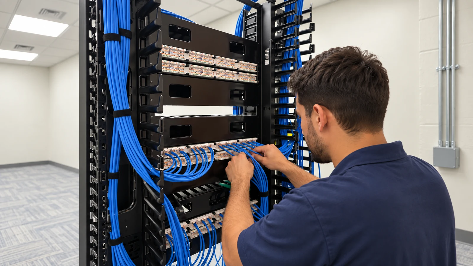
Switches, optics and uplink configuration terminate and use the optical backbone.
View Network Solutions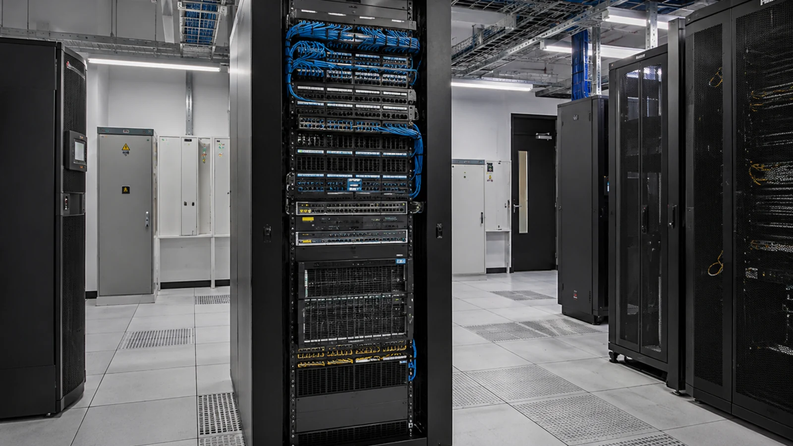
Copper horizontal links serve local endpoints while fiber carries the backbone between rooms or buildings.
View Cabling Services
Remote camera segments may use fiber for transport while camera streams and recording remain a camera-service design.
View IP Video SurveillanceRELATED PATHS
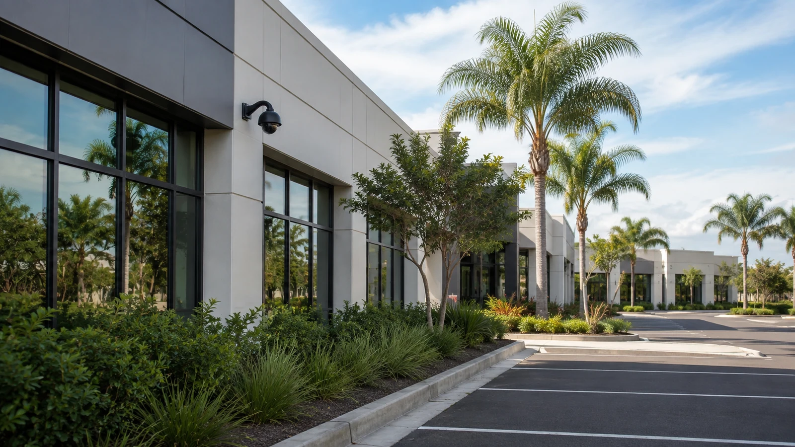
Optical backbones connect telecom rooms and detached facilities.
Explore Campuses and Multi-Building Sites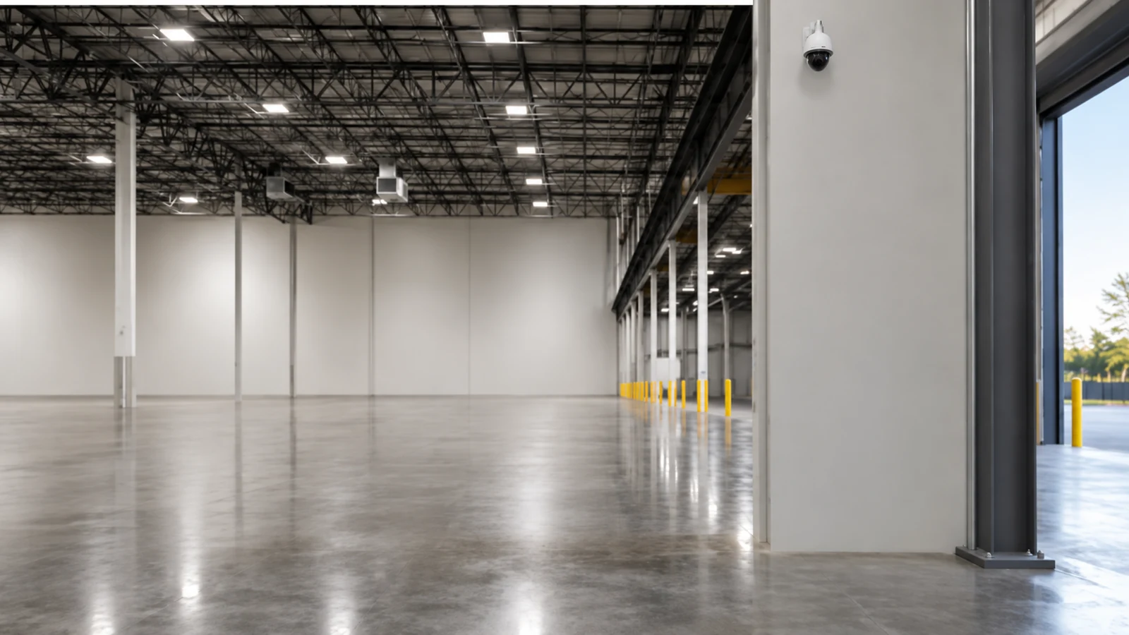
Distance and electrical environment can favor fiber for uplinks.
Explore Warehouses and Industrial Properties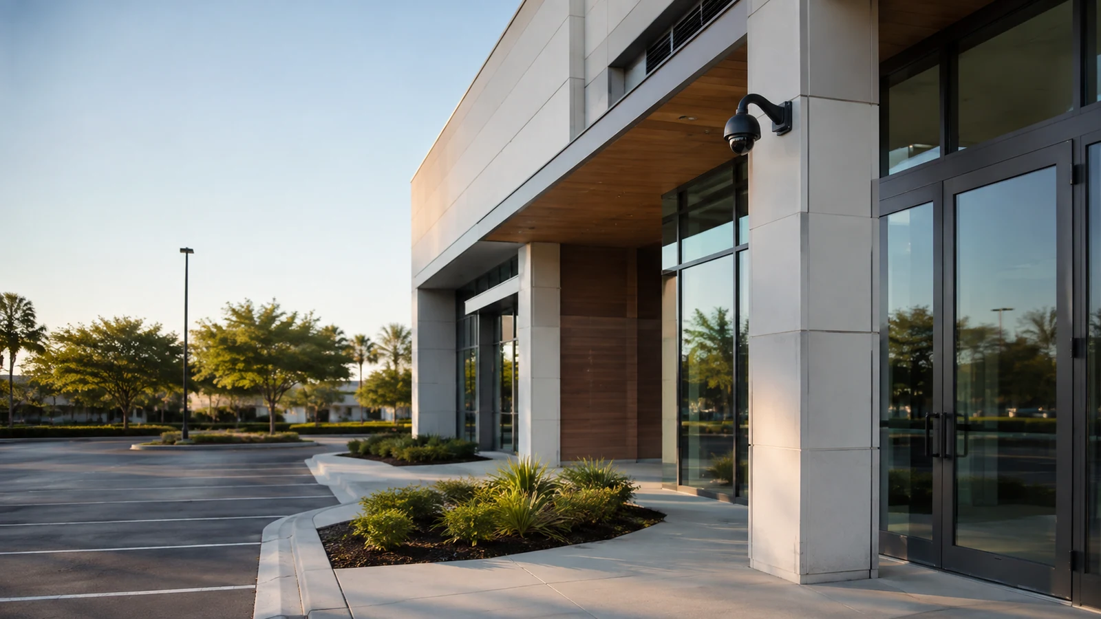
Spare strands and documented enclosures make future expansion more practical.
Explore Growing Commercial FacilitiesPROJECT PROCESS
Survey endpoints, distance, pathway, environment, fiber type, strand count and enclosure locations.
Place the approved cable with bend and pull control, then organize slack and enclosure entry.
Complete supported optical connections, label every strand and connect the approved interface path.
Measure the agreed optical path, correct unacceptable results and deliver strand, splice and test records.
LICENSED SUPPORT
Data Pro Communications operates under FL License #EC13016138. Fiber work is handed over with strand assignments, enclosure and patch records, interface boundaries and the agreed optical loss evidence for the installed path.
FAQ
Single-mode is commonly selected for longer distances, building backbones and lifecycle flexibility, but optics, installed plant, cost and the required link should determine the choice.
Multimode can support shorter in-building or campus links with compatible optics. The fiber grade, distance, wavelength and bandwidth requirement must align.
Count the active pairs, planned growth, redundancy and restoration needs, then document spare strands. The answer depends on topology and the services using the backbone.
It is the maximum end-to-end attenuation the selected transceivers can tolerate with appropriate design margin. Fiber length, connectors and splices all consume part of that budget.
Dust and residue can increase loss or damage mated surfaces. Inspection and cleaning are basic steps before accepting a connector result.
An end-to-end light-source and power-meter test measures total attenuation at the selected wavelength. Other methods, such as OTDR testing, answer different location and event questions when included in scope.
Reuse depends on fiber type, route, connector condition, test results, available strands, labeling, optics compatibility and whether the path meets the required loss and capacity.
Records should identify cable, enclosure, tray or cassette, strand color or number, endpoint, patch-panel position, service assignment and spare status.
Fiber can carry the network uplink serving remote IP cameras when switches, optics, power and network design are coordinated. The optical backbone and camera configuration remain distinct scopes.
Provide route and endpoint records, fiber type and strand count, splice and enclosure details, patch assignments, measured loss, test wavelength, exceptions and the active-interface boundary.
Describe the endpoints, distance, route, existing fiber and equipment interfaces. A backbone survey can define fiber type, strand plan, enclosures and test evidence for the optical path.